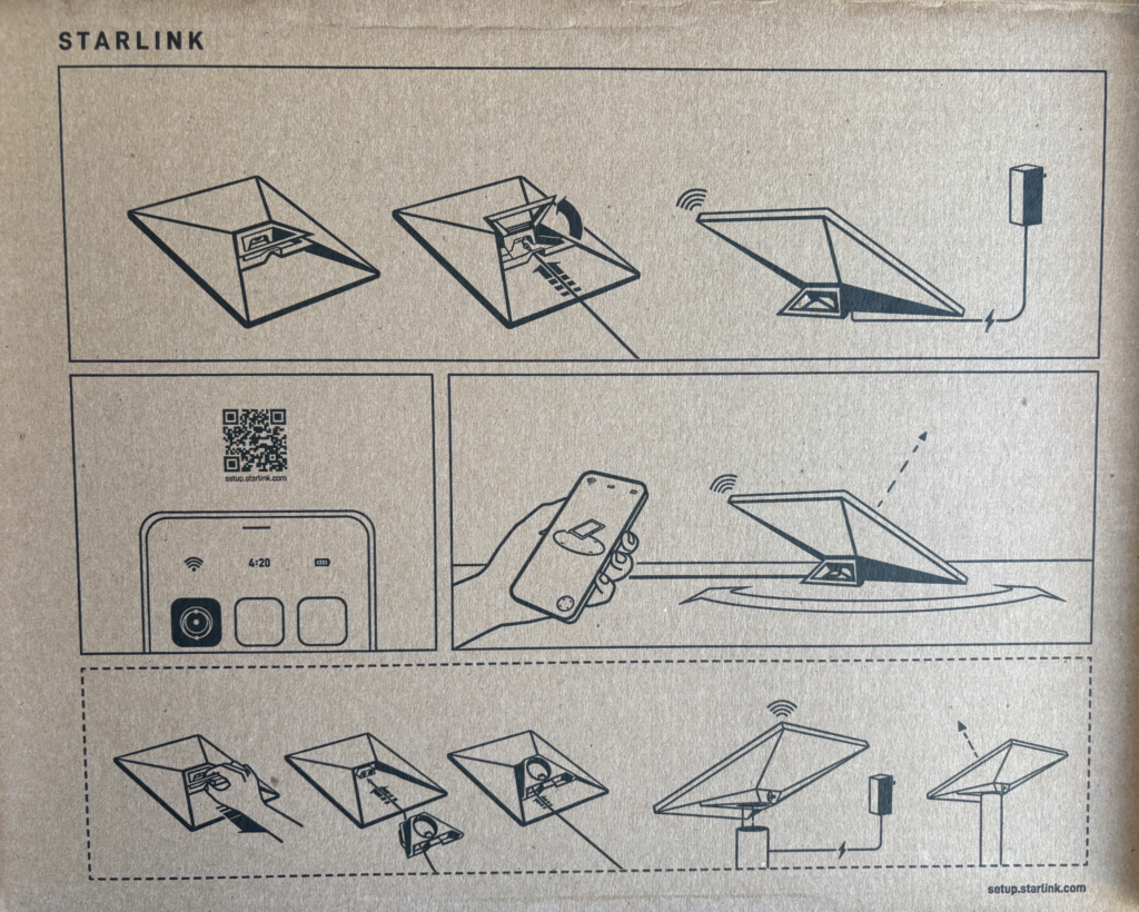
Ordered for our Canal Boat from Currys a couple of days ago for delivery to our local store for collection, the process could not have been simpler.
Once home, it was time to open the box, inside we find on the inside of the lid some simple getting started instructions, it the base are all the bits you need to get started (Well almost – more on that later).
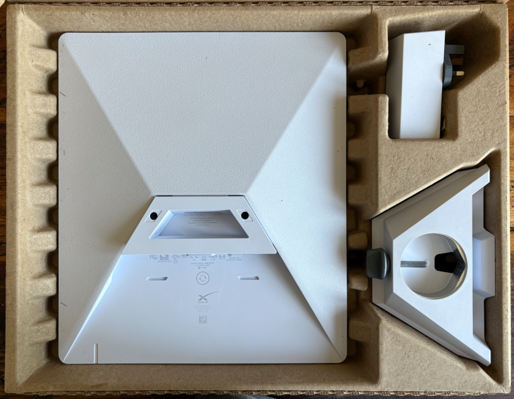
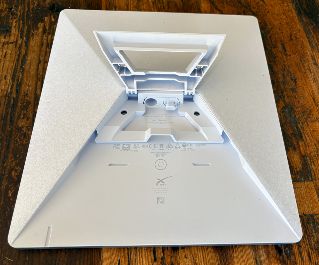
On the image above we can see the back of the StarLink Mini, the UK power supply and the Pipe mount.
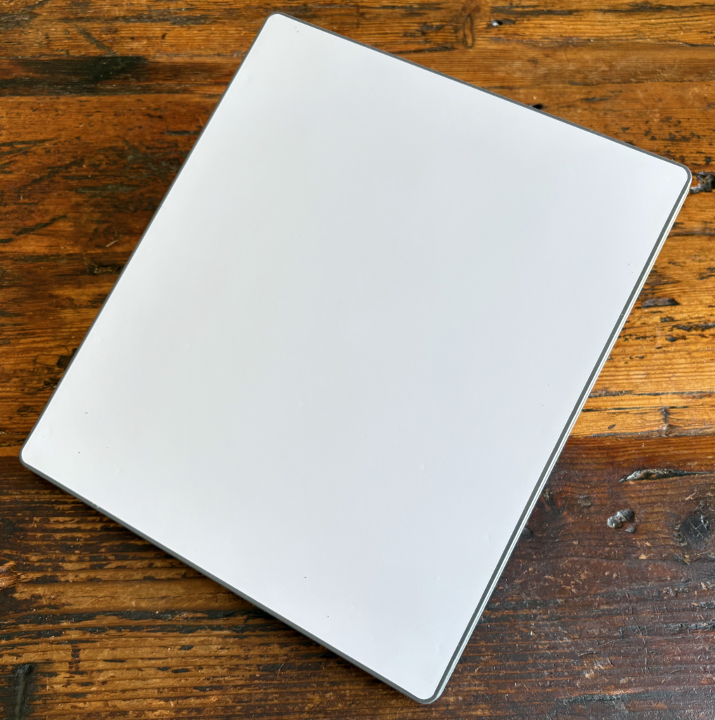
The StarLink Mini is approx 29cm X 26cm and comes with the kick stand installed, as can be seen above.
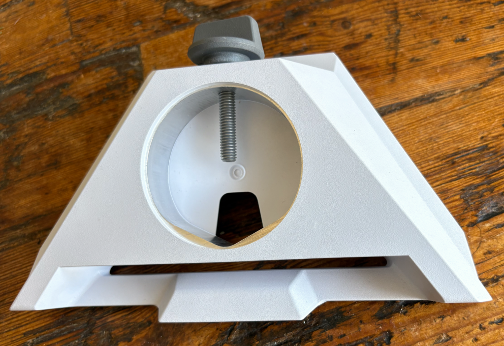
Included in the box is the Pipe mount, this replaces the kick stand and can be mounted on pipes 31 mm (1.25 inches) to 50 mm (2 inches).
There are lots of mounting system that use this adapter, I have also seen Tripod adapters that fit in the mount providing a standard camera tripod socket.
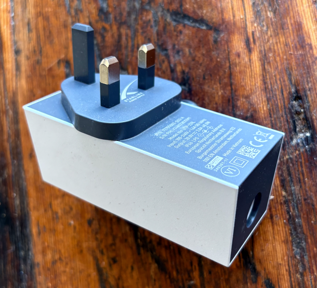
The power supply for the UK is the standard 3 Pin plug, it can take input from 100-240v 1.6 Amps at 50/60Hz.
Output is 30v 2 Amps (60W).
It is unlikely we will use this onboard as we try to minimise the use of our 240v supply as our inverter so ineffiecent for such a small load. (Our inverter was installed so we could use a Washing Machine and power tools when needed and can output 3000W.
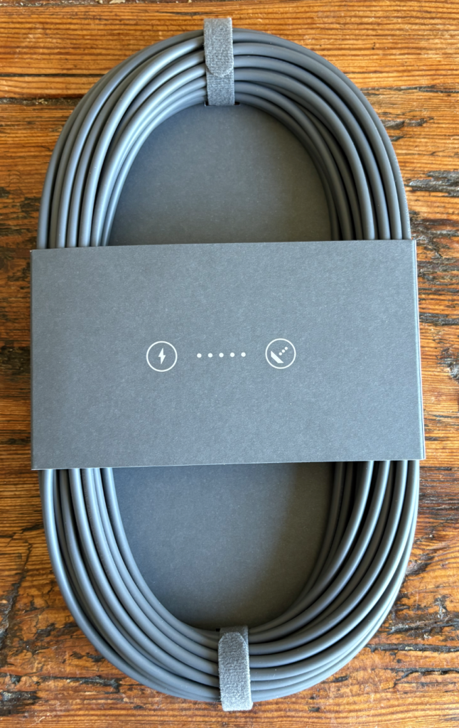
The 15m (approx 50ft) power lead supplied is nice and long and is designed for use with the mains adapter, it has a special water tight connector at each end.
It is again unlikely we will use this on the boat, as I hope to run the system on 48V using a power over Ethernet solution (More on that later)
As well as a power plug on the back of the StarLink Mini there is also a Ethernet RJ45 which we will use to get the network inside to our boat WIFI. The StarLink has it own built in WIFI, but this is probably not be very effective on our all steel narrow boat (we will test this once we have it all installed on the boat.
We have a few more bits on order including a POE (Power Over Ethernet) adapter and power supply and some external high quality ethernet cable.
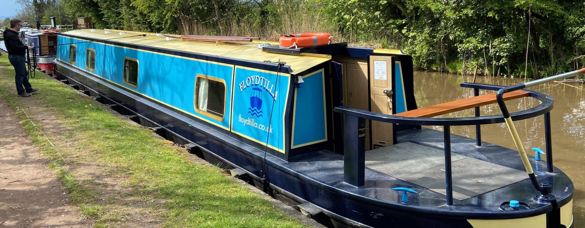
We have just purchased a StarLink Mini from Curry’s for £189, they were £399 just a short while ago so once we are back on the boat at the end of August for our next trip, we will do a series on how to install this on the roof of our Canal Boat, what options are available and how to power successfully from 12v.
Starlink Mini from Currys £189
There are a number of options we are looking at for the roof mounting, we don’t want it to be a permanent fixture as this will also be used in other locations, but magnetic and suction mounts are a possibility. We also expect to remove the panel when we are not on the boat if needed.
The monthly running costs of a StarLink system are not cheap, but the ability to connect in remote locations is a big plus point for us when we travel.
So we had a problem with our installation of the new Heatmiser thermostat. The thermostat is now positioned half way along the boat, before the old thermostat has been in probably the coldest part of the boa, much nearer the original heater controls. Now when the batteries are not fully charged the voltage drop on the 1 mm2 cable can to great to make the Eberspacher Diesel heater fire up reliably.
Problem solved by adding a remote relay
To fix this problem we needed to fit a relay where the old thermostat was positioned and use the Heatmiser thermostat ‘Call for heat’ signal to switch the relay, which would intern switch on the diesel heater.
Heatmiser with Relay
The new wiring looks like the diagram above, with the relay much nearer to the heater there is minimal voltage drop from the relay to the heater, while the Heatmiser thermostat is still happy.
The relays I purchased at 12v automotive spec with a way over the top 30A switch capability. They come with a 30A fuse, this is replaced with a 1A fuse for this installation.
I have been looking for a digital thermostat programmer for use on the boat and while browsing eBay I found a Heatmiser neo Stat 12V V2 for auction, that seemed a little cheap so I put a bid on it at up to £20, in the end it cost me just £20.57 including delivery and buyers protection.
The 12v version is rare on eBay and when I see them they are going at about £50+ and new they are over £75.
Things I liked about the Heatmiser neo Stat 12V V2 was its ability to add control over the internet with a neoHub at a later date ( I did check the neoHub uses a 240v to 12V wall adapter, so should be no problem being adapted for the boat).
The heating control options also seem to cover most of the eventualities I could foresee including Weekday/Weekend and 7 individual day timing options, multiple (4) daily settings (they call them comfort levels) as well as 24 hours mode (good for us retired boaters, as weekend don’t have the same meaning anymore) and finally a non-programmable option where I can use this just like a basic old style thermostat and just set a temperature as I need it.
The only option that did not suit that well was the Frost Thermostat option which only goes down as low as 7° which on our boat we would like to be closer to 1-2° so we don’t waste to much diesel in the winter.
What we have now
At present we have two older style mechanical thermostats and the original push pull heating switch that Black Prince use. We fitted the thermostats as a quick and dirty upgrade, they are both mechanical devices one where you rotate a dial to the temperature you require, the other is our Frost Thermostat, which can be set to very low temperatures. The plan is to keep the original frost thermostat which we will continue to use.
When I installed them I added switch to enable me to be able to select if they are connected.
The biggest problem was that these thermostats where installed near the back door, which is OK for the Frost Thermostat, but for the Heating Thermostat that was probably the coldest place on the boat, so the heating could be on and the main cabin area would be 20°+ degrees, but the Thermostat was reading just 17°-18°.
The New Install
The first job was to find a place on the wall at approx head hight that would not be easy to walk into (in a house not normally a problem, but canal boat walls lean in) while also being away from radiators and not in direct sun light. Having found what looks like the perfect place. I had already picked up a Appleby 1-Gang Dry Lining Knockout 35mm deep wallbox, so I used the back of this to mark a square on the wall ready to cut out.
Behind the wall covering was a plywood sheet and behind that was a 35mm approx polystyrene layer, unfortunately or fortunately there was a metal box section just above the hole, making it impossible to push the wire up to the ceiling , so we cut a line in the wall covering and peeled it back then cut a slot in the plywood over the steel box section for the wire to pass over.
The wire we are using is a White PVC four core 1mm2 from Screw Fix as we have polystyrene insulation we need to cover the PVC wire, as the plasticizer in the PVC can react with the insulation hardening the PVC causing it to become brittle and crack. We used clear packing tape to do this.
The cable was then placed behind the ceiling skirting board, which is screwed to a batten and covers the join between the ceiling and the walls. We had previously put some trunking under here for the solar panel cables.
This runs all the way to the services cupboard where we have the old thermostat that this is replacing.
With the cable installed we are ready to wire it all up.
Ceiling Skirting
Wiring up the Heatmiser neo Stat 12V V2
We need to supply the Heatmiser neo Stat 12V V2 with a 12v supply to the + and – terminals and then also the from the A2 terminal we return the “Call for Heat” signal to the Eberspacher D4W Hydronic On/Off control.
Heatmiser neo Stat 12V V2 Thermostat Wiring
The Brown wire in 12V also feeds the A1 terminal which is one side of the ‘Call for Heat’ relay, then the Black wire in the 0V and finally the Grey wire will supply 12V back to the Eberspacher when the Heatmiser calls for heat.
Heatmiser Wiring Diagram
Now this all worked perfectly when I wired it all up, but come the morning and we had no heat, the Heatmiser was working displaying as normal and calling for heat, but nothing was happening, when I pulled the original heating on button, the heating fired up…
What is going wrong?
So what I think was happening is the extension of the cables from the services cupboard to the Heatmiser even with the 1mm2 cables combined with some Voltage drop on the leisure batteries was lowering the voltage to the Eberspacher heater below what it required (Remember the 12V supply is then returned on the A2 line back to the Eberspacher, in effect doubling the cable length (probably 30ft of cable in total).
Had the engine been on or the solar panels working, we would not have seen the problem,
The fix for this should be simple but that will be a job for my next visit to the boat, as the weather is getting warmer it is not a problem and I have to head home.
We use cookies on our website to give you the most relevant experience by remembering your preferences and repeat visits. By clicking “Accept”, you consent to the use of ALL the cookies.
This website uses cookies to improve your experience while you navigate through the website. Out of these, the cookies that are categorized as necessary are stored on your browser as they are essential for the working of basic functionalities of the website. We also use third-party cookies that help us analyze and understand how you use this website. These cookies will be stored in your browser only with your consent. You also have the option to opt-out of these cookies. But opting out of some of these cookies may affect your browsing experience.
Necessary cookies are absolutely essential for the website to function properly. These cookies ensure basic functionalities and security features of the website, anonymously.
Cookie
Duration
Description
cookielawinfo-checbox-analytics
11 months
This cookie is set by GDPR Cookie Consent plugin. The cookie is used to store the user consent for the cookies in the category "Analytics".
cookielawinfo-checbox-functional
11 months
The cookie is set by GDPR cookie consent to record the user consent for the cookies in the category "Functional".
cookielawinfo-checbox-others
11 months
This cookie is set by GDPR Cookie Consent plugin. The cookie is used to store the user consent for the cookies in the category "Other.
cookielawinfo-checkbox-necessary
11 months
This cookie is set by GDPR Cookie Consent plugin. The cookies is used to store the user consent for the cookies in the category "Necessary".
cookielawinfo-checkbox-performance
11 months
This cookie is set by GDPR Cookie Consent plugin. The cookie is used to store the user consent for the cookies in the category "Performance".
viewed_cookie_policy
11 months
The cookie is set by the GDPR Cookie Consent plugin and is used to store whether or not user has consented to the use of cookies. It does not store any personal data.
Functional cookies help to perform certain functionalities like sharing the content of the website on social media platforms, collect feedbacks, and other third-party features.
Performance cookies are used to understand and analyze the key performance indexes of the website which helps in delivering a better user experience for the visitors.
Analytical cookies are used to understand how visitors interact with the website. These cookies help provide information on metrics the number of visitors, bounce rate, traffic source, etc.
Advertisement cookies are used to provide visitors with relevant ads and marketing campaigns. These cookies track visitors across websites and collect information to provide customized ads.