
The problem has always been: How much water do I have it the tank? This is part 3, the development of our solution.
Software development is now pretty much complete, and the User Interface is detailed below. Next will come the installation process, but this will have to wait till warmer weather.
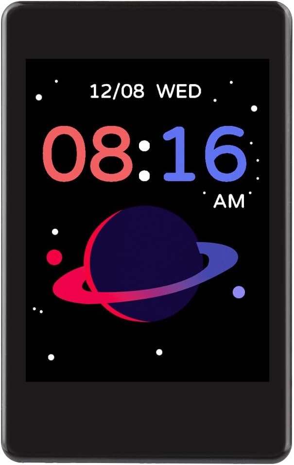
The User Interface (via a small 320X240 touch display) in the cabin.
After a bit of a promotional splash screen the water meter starts on its main information screen.
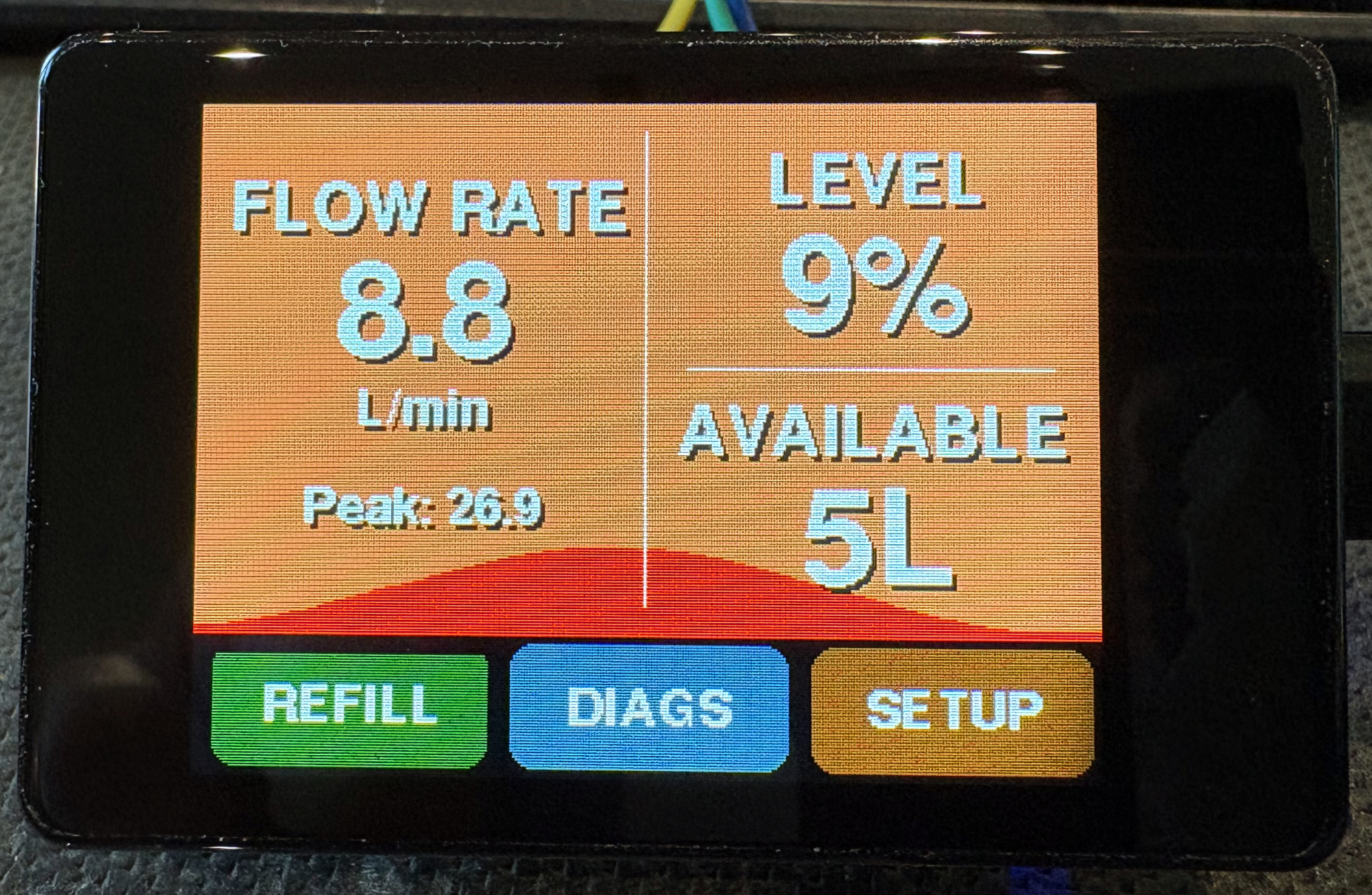
This quickly shows you the important information, The tank level as a % and the number of litres available, also included is the current flow rate in litres per minute and just for the hell of it the peak flow rate.
The three buttons across the bottom are our main navigation: the REFILL button does just that and should be used once the tank has been refilled, it will reset the tank back to 100% full. BUT it is very easy to just press this button, so to make it operate you need to hold it for 3 seconds and then you will be asked if you want to refill the tank with a Yes/No option.
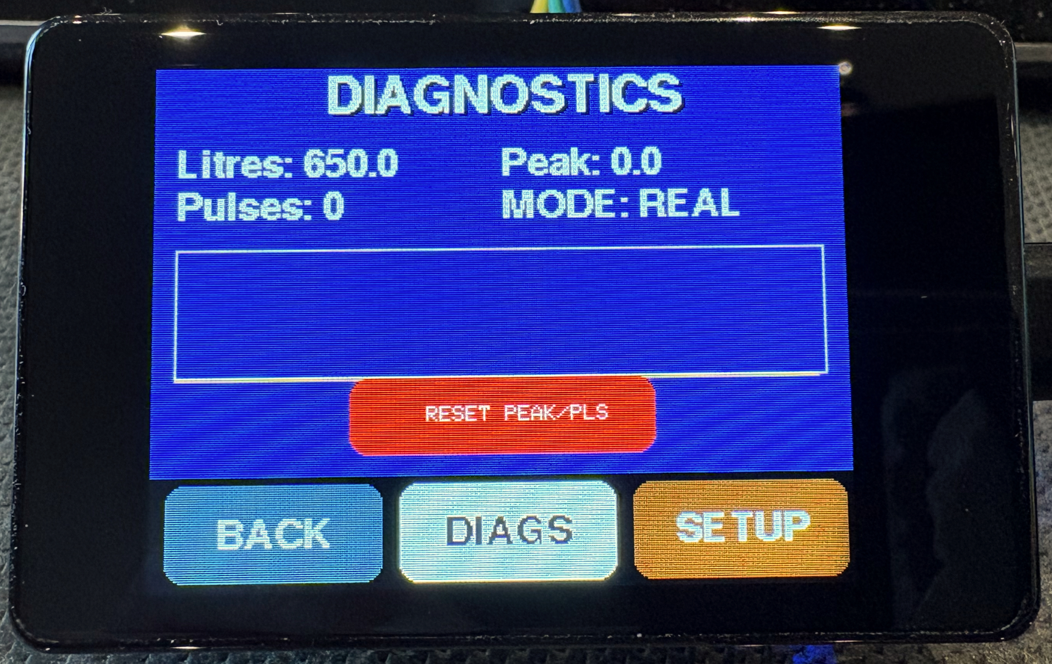
The DIAGS button takes you to a new screen that has a few options, like seeing the number of pulses the meter has counted since the last reset. This is very useful to help setup the meter so it knows how many pulses there are to a litre. On mine it is 644.
I found this out by measuring 5L of water pass the Flow Sensor a few times and calculating an average per litre.
The pulse counter is reset using the big red RESET button.
On this screen is a MODE: display, if you touch the DIAGS button again you will put the meter into DEMO mode, this was added during development of the user interface (UI) so I could see how everything operated, it simulates flow and reduces the volume in the now smaller tank.
The box above the reset button is a graph of the flow over approx the last 30 seconds, it self scales, so only useful as a guide/fun.
P.S. to get out of DEMO mode press the DIAGS button again and the system will toggle from REAL to DEMO, it should, when returning from DEMO mode, remember the last water level in the tank so you can try it at any time.
The last button of the three is SETUP, this is where you can customise the setup to your Tank size, the number of pulses per litre, and when to raise the alarm (more on those later).
The timeout option sets how long the display will remain active before switching off (it returns to full brightness when you tap anywhere on the display.
The last option on the right LAND can be used to switch the display from landscape to portrait mode, so when you mount this you have the choice.
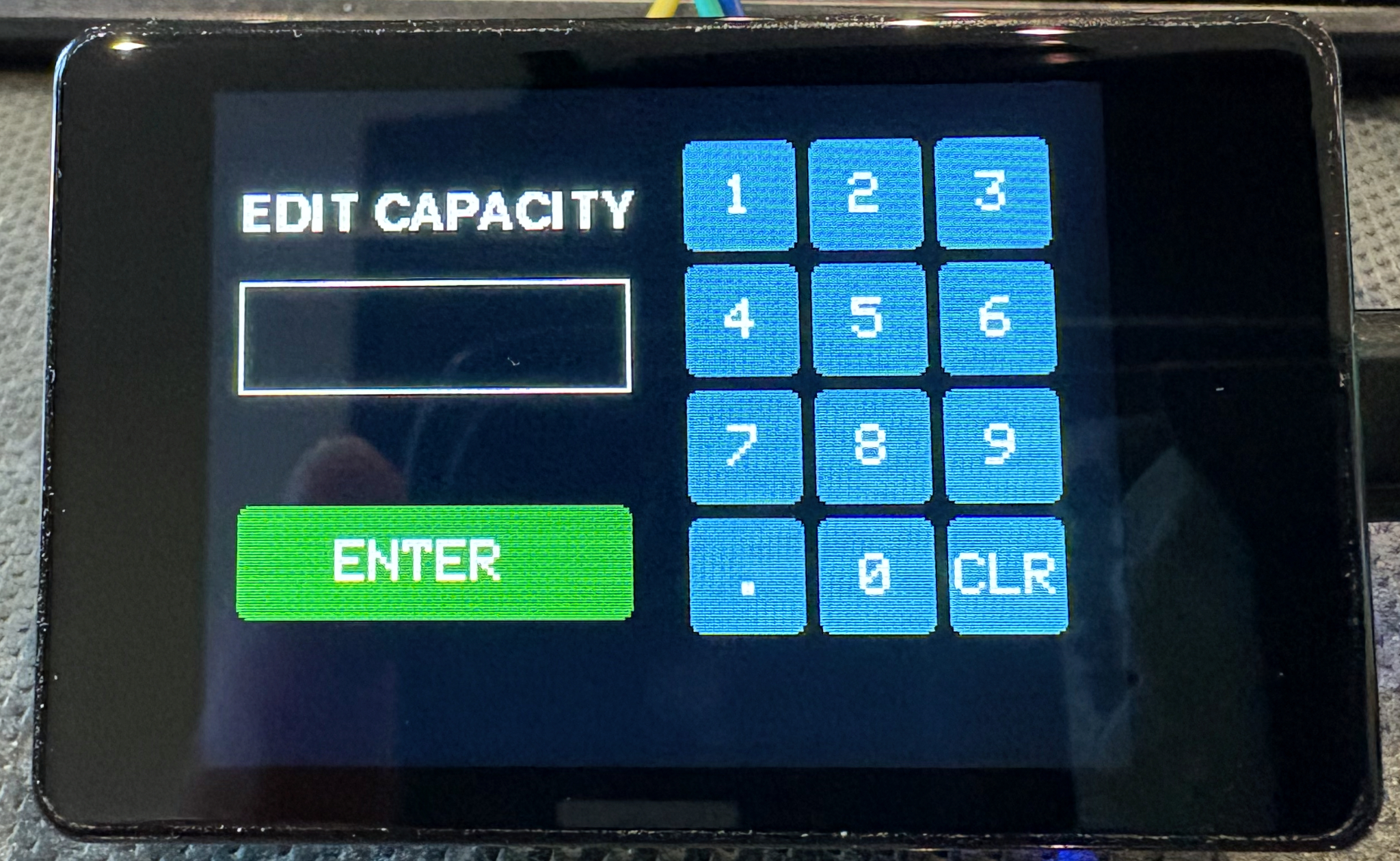
If you tap on a setting box the system will display an edit page where you can enter the relevant value. If you don’t want to change a value just make sure the input is empty and press the green ENTER button
The display in use
For a bit of fun I added a moving wave in the background graphic, but the light blue / dark blue is also an indication of the remaining water level.
Another setting you can adjust are the warning levels by default at 30% remaining the background wave turns yellow
The last warning by default at 10% the wave turns red
The display will switch off if left untouched, but it will wake to 10% brightness if the sensor detects any water flow. I did not want to have the display too bright at night, but I did want to know if water was flowing.
To see what happens I decided to give an AI a shot at assisting me with the code development. The chosen AI this time was Gemini from google (Other code writing AI’s are available).
What had to do first was write down what I wanted the AI to produce, what IDE (Arduino) I was using, the hardware configurations, boards and accessories and how they are wired together.
Example question to AI – “I have a ESP32-C6-Touch-AMOLED-1.32 board that I am using the Arduino IDE to program, can you create a simple test program to see if the display is working”
This example use the wrong driver chip type for the display it had used the SH8601 instead of the GC9A01, after finding this and another few attempts we had the screen working and we could write things on the display.
After getting the display working, I asked it count the pulses from the flow sensor, and using my best guess of 450 pulses per litre, calculate the amount of water that had passed since it was powered on.
Next I added a button to GP2 (pin 7), this for testing was a cheap push button, the other side of which was connected to GND (pin 20), this was used to reset the volume of water in the tank available back to full, but to make is hard to do by accidentally you needed to press it five time with less that a second between presses.
As you can see the connector are very small the pitch between sockets is just 1.27mm, much smaller than the normal 2.54mm pitch I am used to. This becomes a problem later as finding a connector to fit this, but at the moment I am pushing single core wire directly into it.
Restarting with a new board.
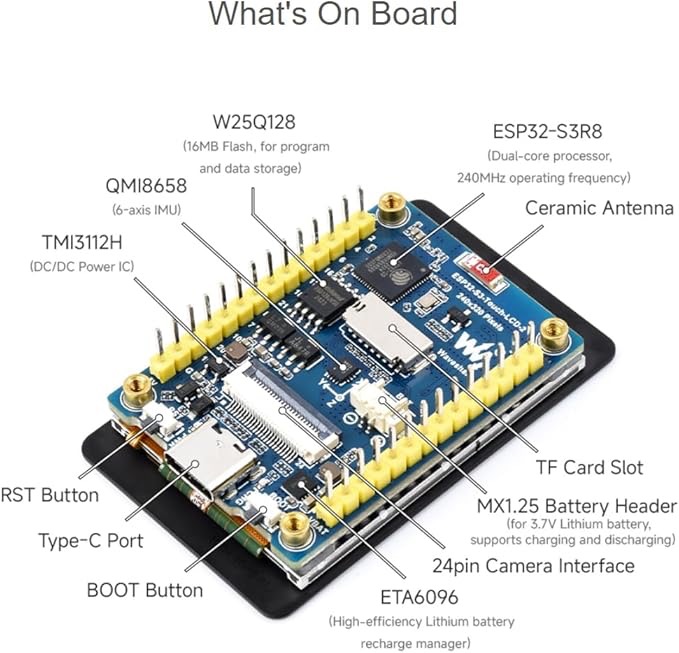
While the original board was working I really wished I had got a touch screen, so I decided to change the display to a Wave Share ESP32-S3-Touch-LCD-2, this has advantage of a larger 2 inch display with a resolution of 240×320, by favourite features was the touch display and the larger 2.54mm spaced pins on the back.
ESP32-S3-Touch-LCD-2 Front
ESP32-S3-Touch-LCD-2 back
Now with a better display and a touch screen, I started experimenting with the AI development and I learned a lot about using the free level AI for this type of development.
Only make one update at a time, only ask the AI to make a single up date, don’t be to ambitious and try to add to much at once, it may work, but my experience is that it will not always end well and you may find you have lost features to expected to remain.
TEST, test and test again, after each update make sure it does what you expect and that you sill have what you had before the update still working.
If you get compile time errors, feed then back to the AI, it will probably fix them without a problem.
Circles (going around in), early on when getting things like the display working, it recommended libraries I did not have installed, these can be difficult to get working if they are not designed or modified for your board. I have been around a few hours of created some code, inputting back in the compile errors, to have the AI confidently tell me they next iteration would fix all the problems, only to find a few steps later we where back with the same setting that had failed in the first place – What I tried and it worked for me was to find an example for the board I am using and feed that code into the AI as a working example of say the display working and ask it to try the same methods.
What I did find if I was patient and will to try things and maybe have to revert back to a working version if needed, this method saved be 1000’s of hours of development time and helped me produce a working product, sometimes I had to study the code it produced, but most of the time, you can get it to fix a problem once you understand what could be going wrong.
This is the eternal question normally just before taking a shower or putting on the washing machine. On a boat first hired we had a water gauge, but it did not work very well, most of the time it did not move. When we got our own boat, it did not have a gauge and we tended to fill up as often as we could. I researched retro fitting a sensor in the tank, but it seemed to be a lot of hassle with limited chance of success and a lot of hassle to fit, including cutting a hole in to top of the tank.
Now four years later on I had an idea, I know the capacity of my tank 650 Lts, so if I measure how much I have used after each fill up I should be able to make a good guesstimate of the remaining level.
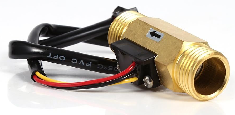
From amazon I purchased for about £15 (approx.$12) a water flow sensor, its maximum water pressure is 1.75MPa (Approx 253 PSI), the range of flow is from 1L/min to 30L/min. I had installed a new pump a couple of years ago and this could output up to 15.1L/min and a pressure of 25 PSI so well within the spec of the flow sensor.
The only specification for the flow sensor I could not find was the number of pulses per litre, what I did find was they seem to operate between 450 and 650 pulses per litre, so I will have to test this later.
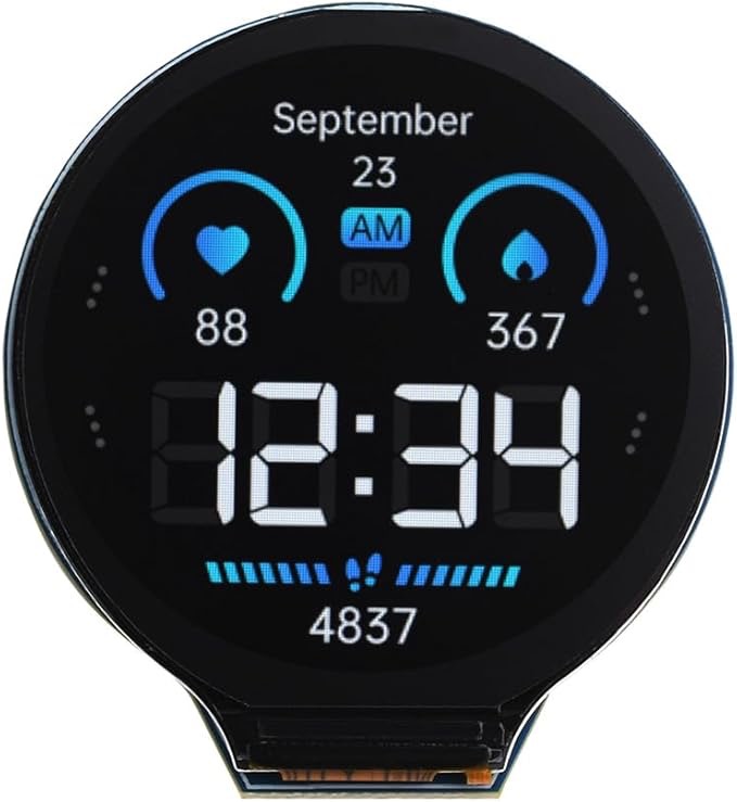
Next I ordered a micro controller with a built in display, I wanted to use the Arduino IDE for the code development as this keeps life simple and I have use it before. On Amazon I found for £20 what looked like a good starting point the Waveshare ESP32-S3 Development Board with 1.28inch Round LCD Display This uses a ESP32-S3 32-bit LX7 Dual-core Processor and includes a GC9A01 Driver Chip for the display.
This information means I can easily find drivers/library for the display and look at other peoples code examples. The manufacturer also provide a wiki full of examples I should have probably pick the one with the touch screen, but more on that later.
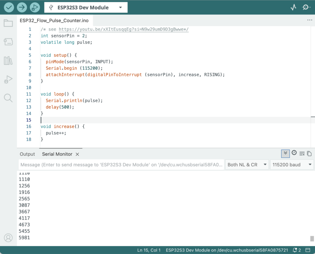
The first code I created was very simple and based on a video on YouTube this enabled me to blow air down the flow sensor and see the pulses on the Arduino IDE serial monitor. Don’t worry if this makes no sense. Basically inside the flow sensor is a small propeller that turns as the water flows past and each time it turns it sends a small electrical pulse up a wire.
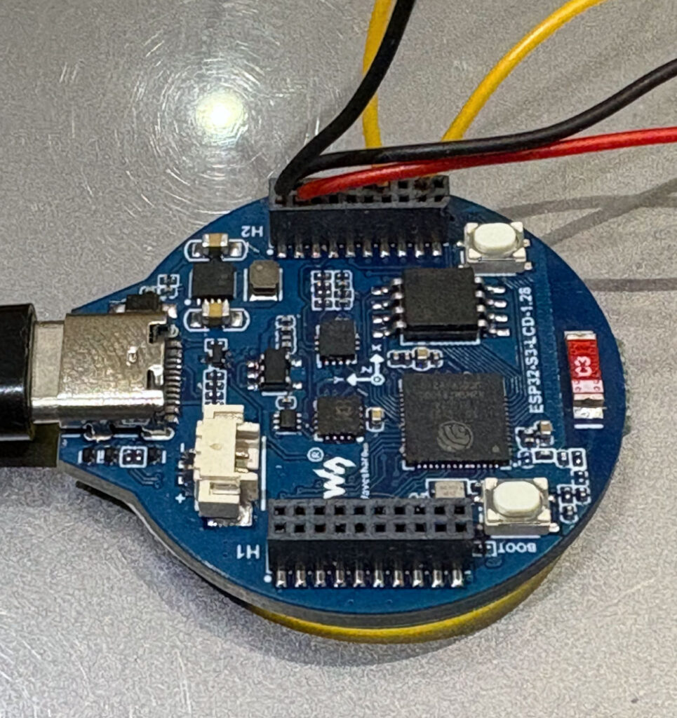
The three wires from the flow sensor a red and black for power and a yellow for the pulse signal I wired to the (General Purpose Input/Output) GPIO pins on the back of the Waveshare ESP32-S3 Development boards H2 connector.
The Red wire goes to pin 18 (VSYS), the Black wire goes to pin 19 (GND) while the yellow wire was routed to pin 3 (GP4).
This was enough with the simple code to see the pulses from the flow sensor display on the Arduino IDE Serial Monitor (This is not generally seen, but can be used by the programmer to output information to see if things are working as expected).
Arduino IDE, Simple Pulse Code
Next we need to get the display working on the board and see if we can output the flow rate, and then add a button so we can reset the system when we add more water to the tank (This is where I wish I had got a display with a touch sensor).
We were almost too late to get tickets for this event. When I booked there were only 10 seats left and only two place where we could sit next to each other. WOW I was surprised as the event was held at The Exchange in Sturminster Newton, which is probably about as far from a canal as you can get.
Robbie Cummings – Canal Boat Stories Sturminster Newton
If you have watched his YouTube Channel or see the TV series Canal Boat Diaries you will know what to expect from Robbie’s presentation style and this even does not disappoint.
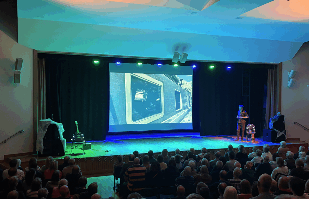
The evening opens with Robbie explaining that he needs to pay for his new windows, but more on that later. We get introduced to his family and friends, being a local boy, many of them were in the audience. Then he covers his journey to buying his canal boat, having borrowed a friend’s boat for a few months.
Robbie Cummings Music – Sturminster Newton
Robbie has a talent for music. At a couple of points during the evening, he demonstrates that with some of the music we recognise from his channel (available to purchase at the end of the evening from the merch table).
After the interlude and the required Purbeck ice cream, he returns with more tales and pictures from the making of the TV series, as well as more about these new wonder windows that have been fitted and that he hopes these events will help pay for…
Robbie Cummings New Boat Windows – Sturminster Newton
Above is a picture of the new double glazed windows installed. It is all a very pleasant evening, a bit like listening to an old friend tell you of his adventures. Robbie has a self deprecating presentation style that puts you at ease, and as a boater, many of this tales are things we could see happening to ourselves.
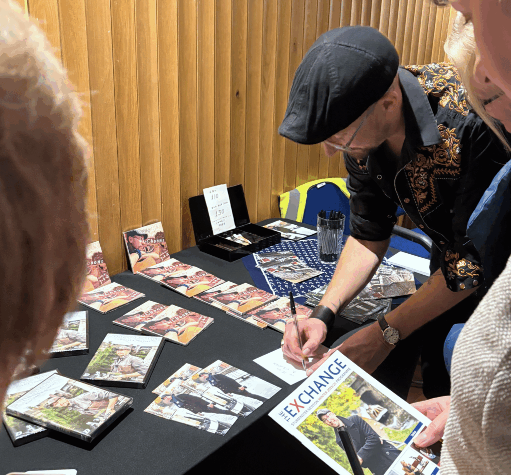
Robbie Cummings Signing – Sturminster Newton
After the show, Robbie stayed and talked while signing his memorabilia for the dedicated fans. We purchased a DVD boxes set of series 1-4, they will come in handy on the boat when our internet signal is too poor for streaming the latest episodes.
David, Robbie & Sonia – Sturminster Newton
We stayed and thanks to Robbie’s mum we got our group picture.
We would throughly recommend going to one of these events they are listed his web site robbiecumming.com. The site includes lots of links to his TV and YouTube work.
The Pen Museum is based in the former pen factory of W. E. Wiley and explains the history of pen nib production and development in an around Birmingham.
The factory was built in 1863 and was named the Albert Works after Queen Victoria’s husband Prince Albert. Production ended in 1876 after a merger with another pen manufacturers Josiah Mason and Perry’s & Co The building was renamed the Argent Centre in 1881 and occupied by silversmith W. J. Myatt.
1. Reception and short history of pen nib production in Birmingham
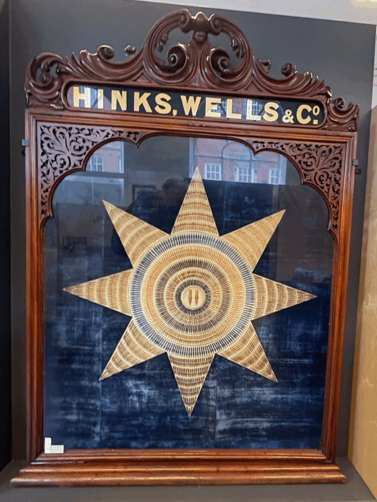
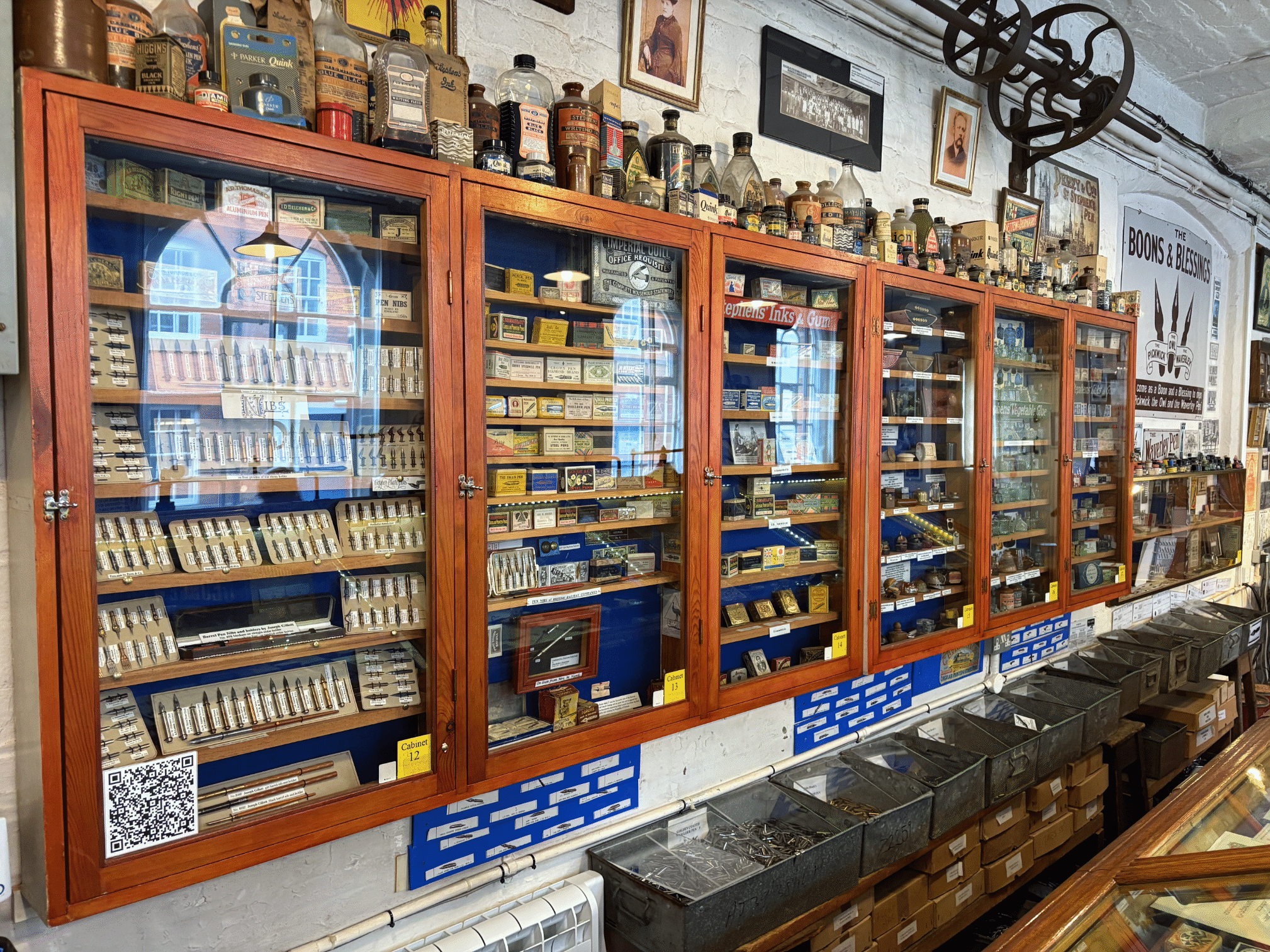
This area is to help you collect your party/group together, there are a number of exhibits and descriptions of the history of Nib production in Birmingham with images and descriptions of the different manufactures
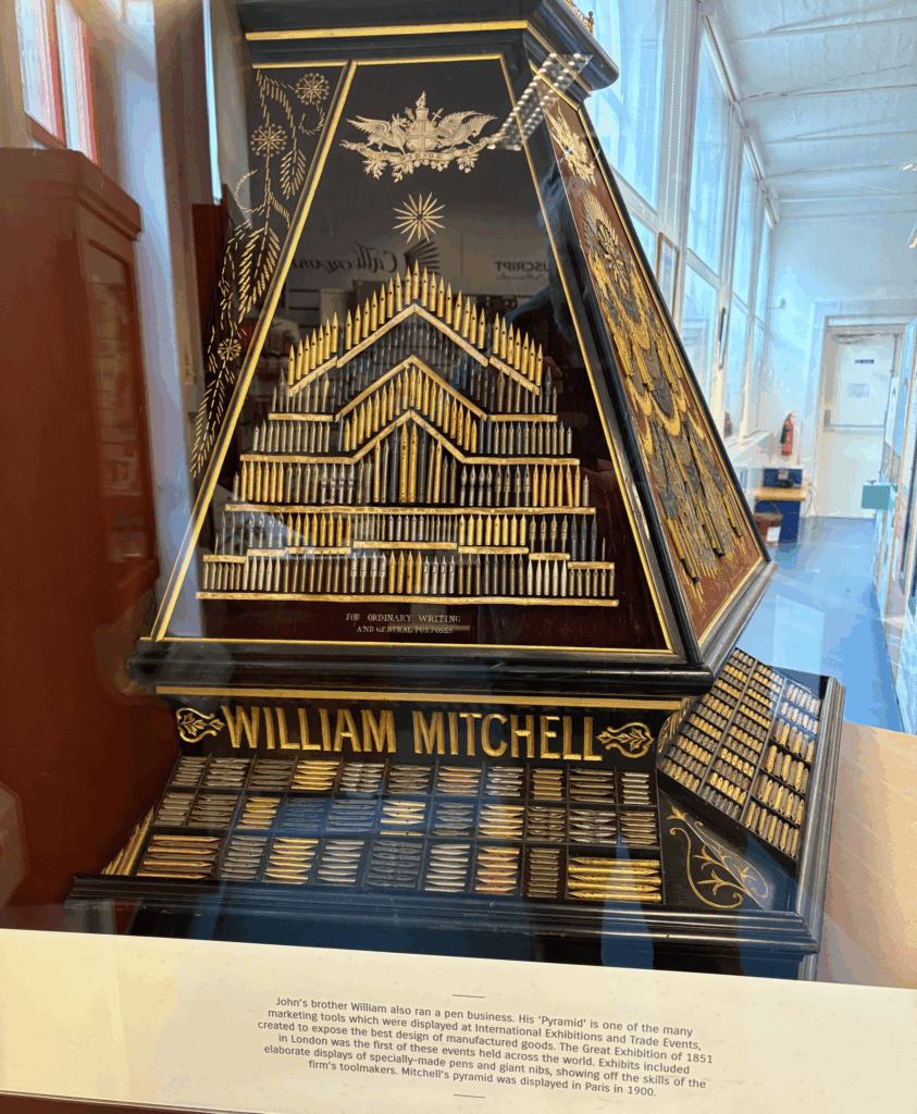
Exhibition Displays of NibsExhibition Displays of Nibs
2. The manufacturing process and demonstration room
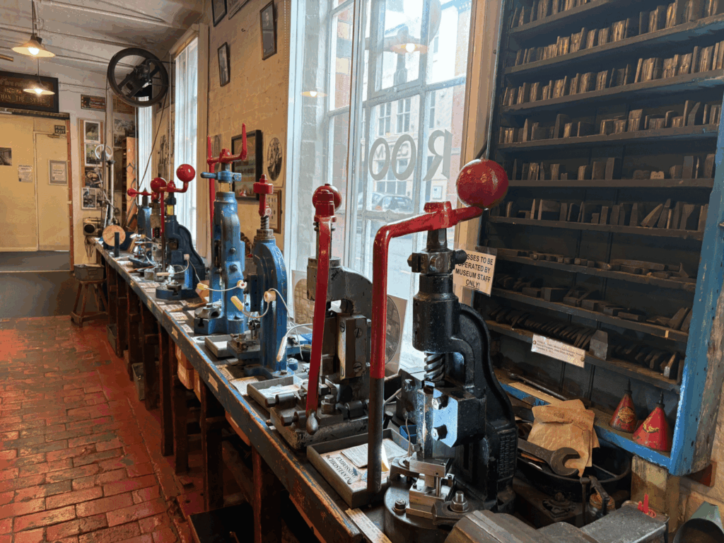
This is where the history and process of making a Nib comes to life
Pen Museum DisplayPen Museum Nib Production Steps
Below is a short video of the first four stages of nib production. Blanking, Piercing, Stamping and Raising, at the end of the video you will see what looks like a finished Nib, but at this stage it would be taken away to be heat treated to harden the steel and then polished in a drum roller.
3. Examples, typewriters, Inkwells and more Nibs Etc
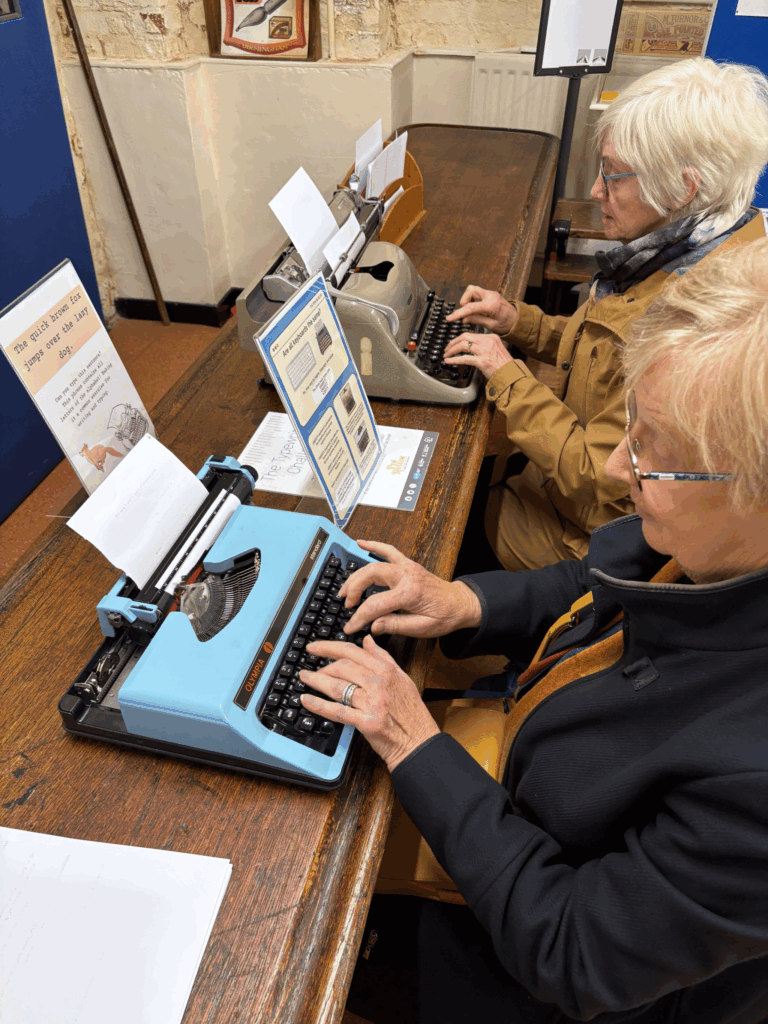
This final room in our tour includes lots of displays and an area you can try out some of the pens, even try your hand at typing on manual typewriters.
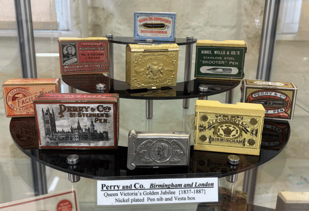
Pen Museum Nib ExamplesPen Museum Perry & Co NibsPen MuseumT ypewriters
After this we returned to the reception area which also contained a small gift shop for purchasing nibs, pens and calligraphy kits.
Before visiting it is best to check the opening time on the website. You can find on the web site times for Calligraphy Workshops and Classes.
The Pen Museum. The Argent Centre, 60 Frederick Street, Birmingham. B1 3HS
Note: This maybe a good Museum to combine with a visit to The Coffin Works are they are just a short 15min walk between and use some of the same techniques and equipment but in very different ways.