“Why do cables matter, they are all just the same, just copper in a plastic tube” this used to be my attitude when prototyping small electronic devices running at 5V on my bench and for 99% of the time I was right, it was not until I got involved in low power DC systems i.e. Power Over Ethernet and fibre that 48V being used as a power distribution system for networking and domestic DC power then voltage drop become an issue.
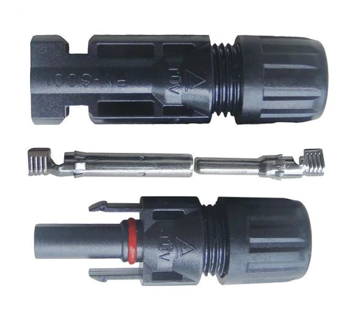
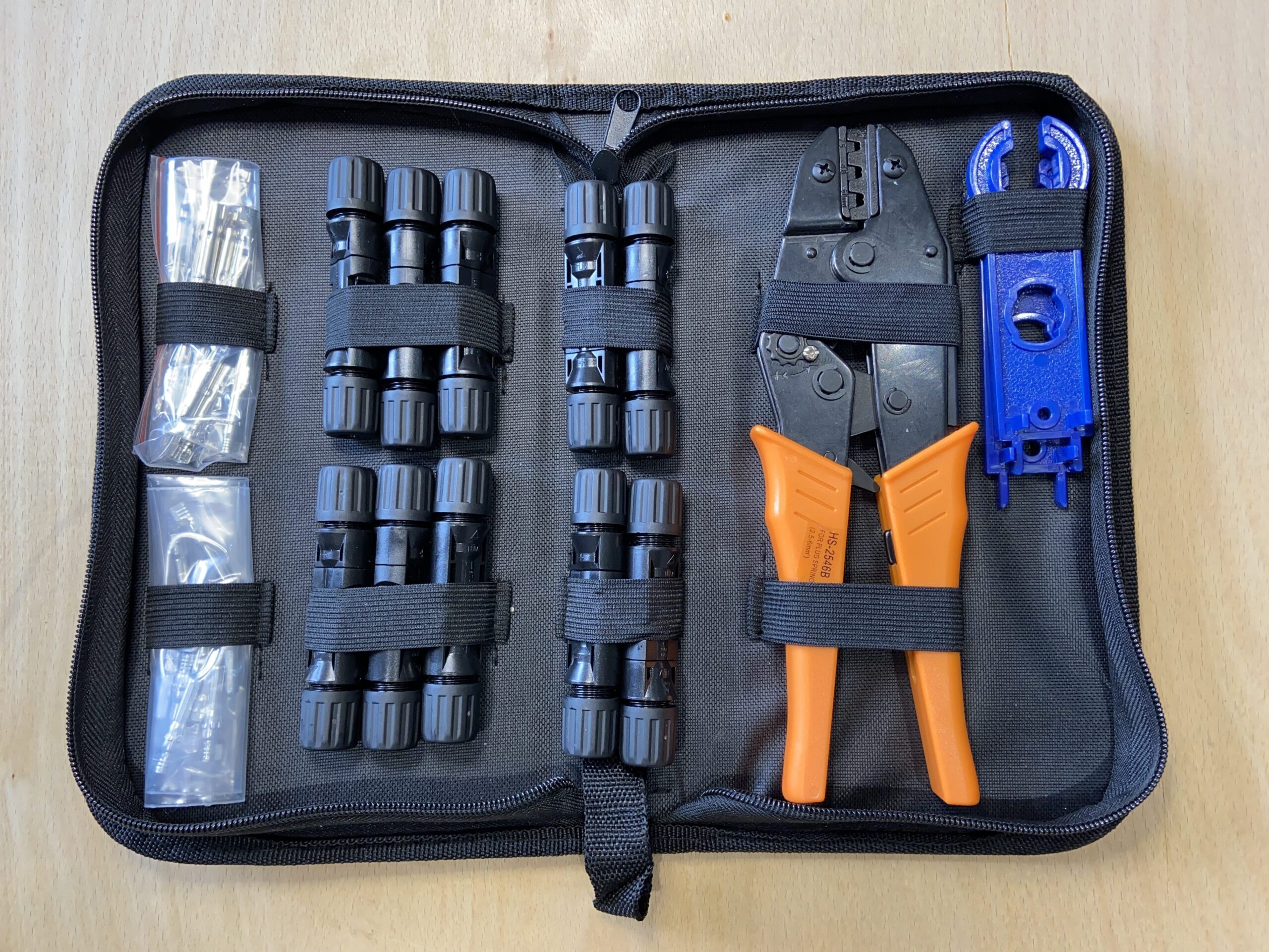
For your Solar Panel wiring, we need stranded wire so it is flexible, it needs to be tin coated so that it does not corrode, especially useful on a boat, then the jacket needs to be UV safe as it is going to be left out in the sun, while also being tough and durable as it will be bent and flexed multiple times.
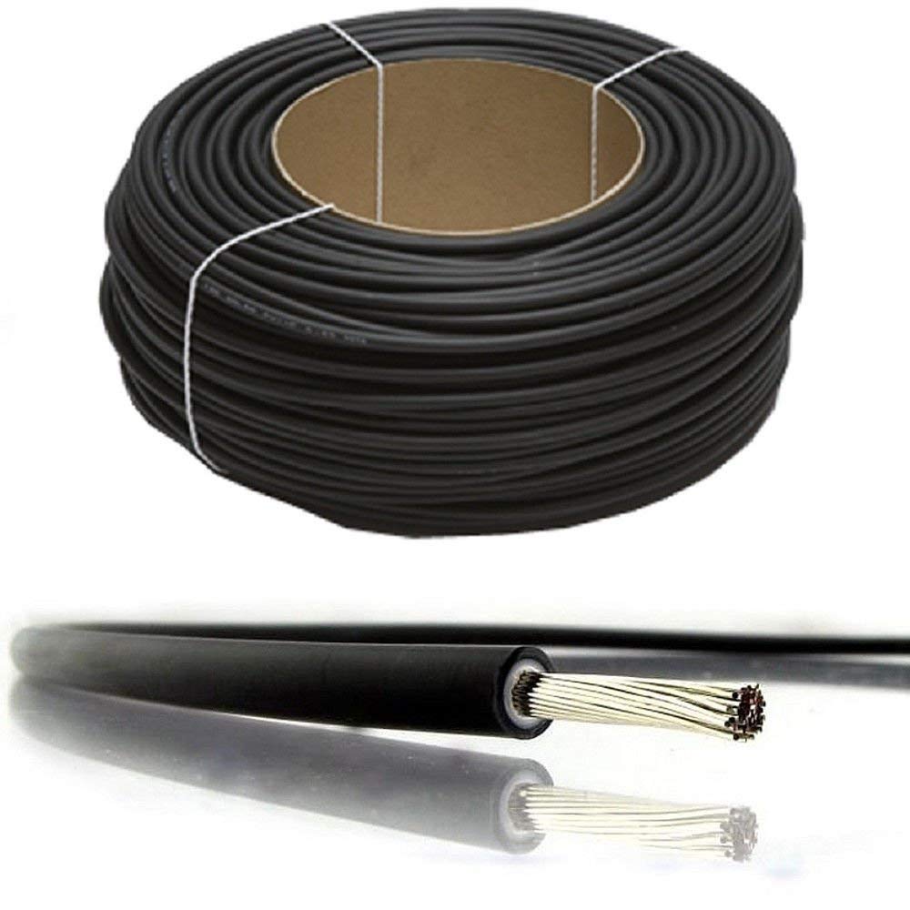
Solar or PV cabling being tin coated means we are not looking at strands of copper that are directly touching each other, each wire in this case has a thin coating of the less conductive Tin, Tin is only 15% as conductive as copper. This has a very slight effect on the resistance of the wire, also being stranded we have a minimal air gap between the strands so 4mm2 of stranded copper wire is not as conducive as 4mm2 of solid copper wire.
When I have calculated the resistance of copper wire in the past I have only used the resistance of pure copper in my calculations, but now things are getting a little more complex.
When planning your install you also have to remember there is a positive and a negative cable in the circuit, so a 20m distance between your solar panels and your MPPT or PWM solar controller is really 40m of cable, so double the resistance.
To enable me to see how much the resistance of the wire changed I originally built an excel spreadsheet that took into account the resistance of the solar stranded tinned copper wire at different diameters in mm2, lucky the manufacturers only make a limited range of diameters of cable for solar systems with 2.5, 4, 6 and 10mm2 being commonly available and they provide the resistance per Km for these.
For your use, I have converted the spreadsheet into some javascript code for this page, so you can input your requirements and see the effect of that cable resistance in terms of Voltage Drop as a value and as a % will have on your plans.
Typically for this kind of DC installation you want a voltage drop of less that 2% is best.
Have a play about and see what is the best cable size/cost is best for your installation
NOTE: This Voltage drop calculator is designed for Solar PV Cable, with Class 5 stranded tinned copper wire, which has a slightly higher resistance than solid copper wire.
Also see
Planning for Solar Panels – Part 1
Planning for Solar Panels Part 2 – Panel Mounting Options
Planning for Solar Panels Part 3 – Types of Panels
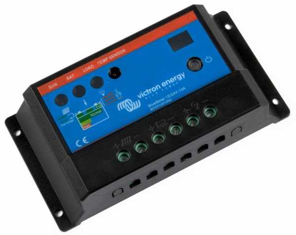
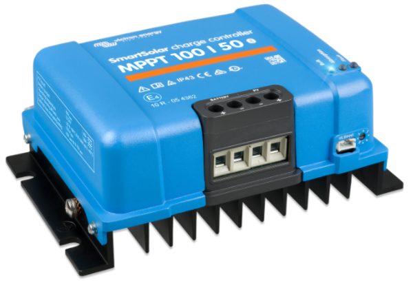
Planning for Solar Panels Part 4 – MPPT vs PWM solar controllers
Planning for Solar Panels part 5 – Cable sizes, lengths and resistance.
Planning for Solar Panels part 6 – Panels in Serial or Parallel
Planning for Solar Panels part 7 – Buying the cable and Circuit breakers
Planning for Solar Panels part 8 – Buying Solar Panels and Mountings
Planning for Solar Panels part 9 – Wiring
Planning for Solar Panels part 10 – Drilling, Tapping and Fitting