
Merry Christmas and a Happy New Year

UK Canal Maps and our Canal Boating Blog
This is the eternal question normally just before taking a shower or putting on the washing machine. On a boat first hired we had a water gauge, but it did not work very well, most of the time it did not move. When we got our own boat, it did not have a gauge and we tended to fill up as often as we could. I researched retro fitting a sensor in the tank, but it seemed to be a lot of hassle with limited chance of success and a lot of hassle to fit, including cutting a hole in to top of the tank.
Now four years later on I had an idea, I know the capacity of my tank 650 Lts, so if I measure how much I have used after each fill up I should be able to make a good guesstimate of the remaining level.
From amazon I purchased for about £15 (approx.$12) a water flow sensor, its maximum water pressure is 1.75MPa (Approx 253 PSI), the range of flow is from 1L/min to 30L/min. I had installed a new pump a couple of years ago and this could output up to 15.1L/min and a pressure of 25 PSI so well within the spec of the flow sensor.
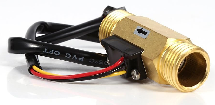
The only specification for the flow sensor I could not find was the number of pulses per litre, what I did find was they seem to operate between 450 and 650 pulses per litre, so I will have to test this later.
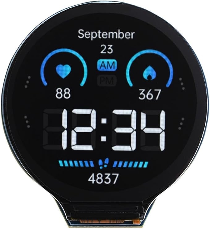 |
Next I ordered a micro controller with a built in display, I wanted to use the Arduino IDE for the code development as this keeps life simple and I have use it before. On Amazon I found for £20 what looked like a good starting point the Waveshare ESP32-S3 Development Board with 1.28inch Round LCD Display This uses a ESP32-S3 32-bit LX7 Dual-core Processor and includes a GC9A01 Driver Chip for the display. This information means I can easily find drivers/library for the display and look at other peoples code examples. The manufacturer also provide a wiki full of examples I should have probably pick the one with the touch screen, but more on that later. |
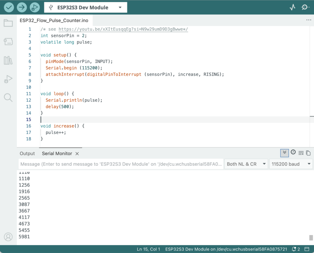
The first code I created was very simple and based on a video on YouTube this enabled me to blow air down the flow sensor and see the pulses on the Arduino IDE serial monitor. Don’t worry if this makes no sense. Basically inside the flow sensor is a small propeller that turns as the water flows past and each time it turns it sends a small electrical pulse up a wire.
The three wires from the flow sensor a red and black for power and a yellow for the pulse signal I wired to the (General Purpose Input/Output) GPIO pins on the back of the Waveshare ESP32-S3 Development boards H2 connector.
The Red wire goes to pin 18 (VSYS), the Black wire goes to pin 19 (GND) while the yellow wire was routed to pin 3 (GP4).
This was enough with the simple code to see the pulses from the flow sensor display on the Arduino IDE Serial Monitor (This is not generally seen, but can be used by the programmer to output information to see if things are working as expected).
Next we need to get the display working on the board and see if we can output the flow rate, and then add a button so we can reset the system when we add more water to the tank (This is where I wish I had got a display with a touch sensor).
While in Birmingham this year we noticed a couple of Accessible Moorings Signs, so started the project to find as many as possible and to produce a map specifically to make them easy to find and also add them to our other maps.
Click here for the Accessible Mooring Map

Now these signs are not everywhere that you find an Accessible mooring, many of them that the CRT have classified as such are just normal visitor moorings that have had their access checked to make sure there are now narrow gates or steps used to get access.
The Accessible Moorings map includes all CRT Accessible locations as well as any Marinas that are listed as having suitable access from the Accessible Waterways Association

If you know of other moorings or services that are suitable for adding to this map please let me know in our Facebook group.