Planning for Solar Panels Part 4 – MPPT vs PWM solar controllers

Lots of acronyms floating about in the solar industry, and as we are looking at Solar Panel controllers we have two more to look at PWM (Pulse Width Modulation) and MPPT (Maximum Power Point Tracking) these acronyms actually describe how each of these controller works.

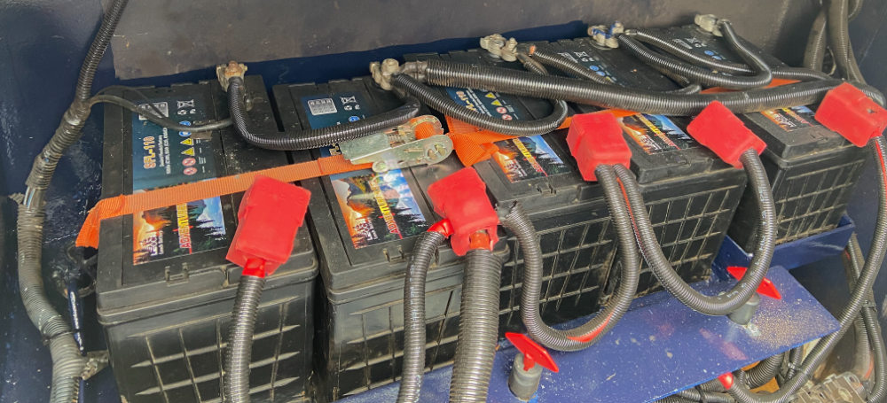
Why do we need a solar panel controller, a 12V solar panel actually outputs between 18-20 volts so to stop your solar panels overcooking your battery we need to control the output to match the best charging voltage for your battery. Lets look at each type of controller see how they work and what the advantages and disadvantages of each have…

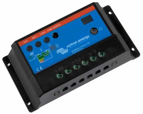
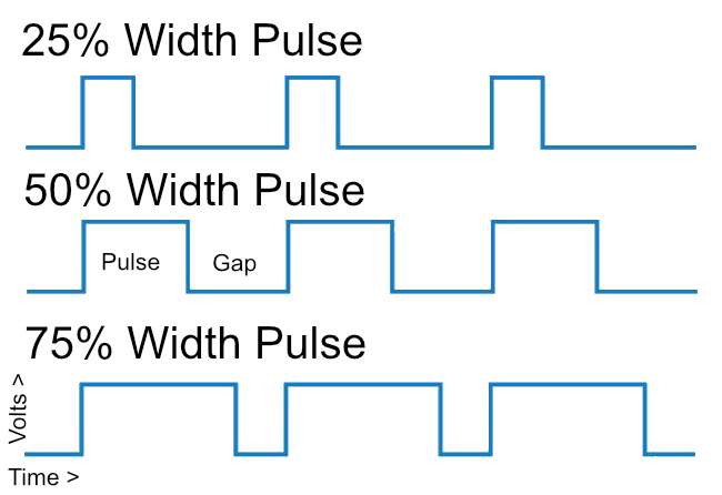
What is PWM – Pulse Width Modulation

Victron PWM Controller

PWM is an robust technology that is used in many devices around your home, I have used this to control motors, dim lights etc etc.

The idea behind PWM is that we take an incoming supply and switch it on and off quickly the difference between the on and the off parts can vary so for example a motor or light that gets a quickly pulsed (25+ timesaver second) at 50% on 50% off a motor will run at ½ speed or a lights output would be 50% dimmer, in these cases the speed of the modulation needs to fast so that the output looks smooth.

PWM Pulse Width Modulation diagram 25,50 and 75 Percent.
Example of PWM at 25, 50 and 75% pulse width.

PWM Controllers act like a switch, with the panels and battery connected the battery will pull the voltage down to its own level. As the battery charges that voltage increases until the batteries are fully charged. At this point the controller starts its float stage, switching on and off the supply from the solar to in effect trickle charge the batteries as required.

The inefficiency of the PWM controller comes from the way it the battery pulls down the supply voltage from the solar panels reducing the available power.

E.G. 100W Solar panel provides 20V at 5A

20V x 5A = 100W*

When pulled down to the battery voltage it is only now supplying 13V at 5A

13V X 5A = 65W*

A loss of potentially 35W or 35%

*These are simplified figures to make the calculation simpler to understand

One of the other major drawbacks of this method is that you are working at lower voltages on the solar panel side of the system as they must match the battery requirement. With lower voltages the cable losses start to add up very quickly, meaning you will need thicker less lossy cables to connect your panels to the controller (We will cover cabling in a later post).

PWM Advantages

• Low Cost 10-25% of MTTP
• Simple reliable technology
• Available in sizes up to ~60 amps

PWM Disadvantages

• Potentially higher cable losses
• Less efficient ~75% conversion
• Solar Panel voltage must match battery nominal voltage.

What is MTTP – Maximum Power Point Tracking

Victron MPPT controller

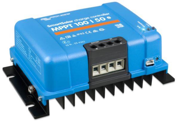
An MTTP controller is divided into two parts, input from the solar panels and output to the battery. The input can take a much higher voltage that what is required charge the batteries. The send part of the MTTP controller, the output will convert this to the correct voltage for your battery to charge correctly (it is a smart DC to DC converter)

So:-

200W Solar panel providing 40V at 5A

40V x 5A = 200W**

This is converted to 13V at 200W increasing the output to 15A

200W / 13V = 15A**

**These are simplified figures to make the calculation simpler to understand and exclude any losses in the dc-dc conversion

A correctly spec’d MPPT controller can accept much higher voltages from the solar panels, so we can use these higher Voltages on the solar side of the system to increase efficiency, and it will drop this voltage to the correct level for the battery current state of charge, it also monitors the panels Maximum Power Point (MPPT = Maximum Power Point Tracking) as it varies during the day to make best use of the power( Watts) available from the solar array.

While being much more efficient for larger systems (<200w) it also enables us to put the panels in series increasing the output voltage of the array therefore allowing us to use thinner cable while maintaining efficiency.

While PWM controllers are rated in Amps as they are fixed to the voltage of the solar panels, a MPPT controller is rated in Watts as they can accept higher input voltages.

Amps X Volts = Watts

50A X 12V Solar Array = 600 Watts

50A X 48V Solar Array = 2400Watts

50A X 100V Solar Array = 5000 Watts

A Watt is the measure of the amount of energy available, as we increase the voltage, we can get more Watts for the same number of Amps supplied.

MPPT Advantages

• Efficient ~95% conversion
• Solar not limited to battery voltage
• More efficient cabling options

MPPT Disadvantages

• Cost significantly more that PWM
• Larger requires more space
• More complex design (less reliable)

Conclusion – Which one will we use?

As you can already probably guessed, we are going for the most efficient 800W+ system we can get and in our case that means using an MPPT controller. We have limited space for panels, but almost no limit on battery size and the necessary equipment storage so the advantages of the MPPT outweigh those of the PWM Controller.

While researching this we did come across a video from Australia that is directly targeted at the Van-life market, but had excellent examples of PWM and MPPT with solar.

Excellent Video on PWM vs MPPT

Also see
Planning for Solar Panels – Part 1
Planning for Solar Panels Part 2 – Panel Mounting Options
Planning for Solar Panels Part 3 – Types of Panels
Planning for Solar Panels Part 4 – MPPT vs PWM solar controllers
Planning for Solar Panels part 5 – Cable sizes, lengths and resistance.
Planning for Solar Panels part 6 – Panels in Serial or Parallel
Planning for Solar Panels part 7 – Buying the cable and Circuit breakers
Planning for Solar Panels part 8 – Buying Solar Panels and Mountings
Planning for Solar Panels part 9 – Wiring
Planning for Solar Panels part 10 – Drilling, Tapping and Fitting

Safety Disclaimer

Installing MC4 Solar Connectors

The MC4 connector has become the standard for connecting to solar panels, it is IP67 rated being both water and dustproof, they are relatively simple to install with the correct tools and luckily these tools and getting cheaper and cheaper.

Most solar panels already come with a male and female MC4 connector already fitted for ease of connection.

These connectors can be used on 2.5mm, 4mm and 6mm single core solar PV cable, it is highly recommended to use the correct cable as the outer sleeve is designed to provide protection from heat, UV, oils, and solvents, it is basically a tough robust cable that is designed for outdoor use.

Today I am going to show you how to crimp on your own MC4 connectors using a cheap crimping tool kit that is available from eBay and amazon.

Click here to order your own MC4 Crimping Kit from Amazon UK

So what we get in your MC4 crimping kit

  • A ratchet crimping tool
  • 2 X MC4 spanners, for assembling and disconnecting the connectors.
  • 10 Compete MC4 plastic male/female connectors bodies.
  • 10 Female metal ferrules and 10 Male metal ferrules  

All you will probably need now is some wire cutters and strippers and you are ready to install your own connectors.

Each MC4 connector is made up from a male and female plastic parts and male and female metal ferrules, the male metal ferrule fits inside the female plastic body and vice versa.

We made a video to show you how simple this can be

How to release the male/female parts

The plastic parts normally come already clipped together, you can use your fingers to release the clips holding the male/female parts together, but it is much simpler and safer to use the two prongs on the end of the blue plastic MC4 spanners provided.

Crimping on the connector

First we need to stripped back the plastic coating to expose approximately an 1/2 inch / 12 mm of the copper wire.

We are now going to crimp on the male metal ferrule.

Push the stripped wire into the ferrule so that the insulation is pressed up to the tabs we are going to crimp.

Then depending on the wire size select the smaller position on the crimp tool for 2.5mm, the middle for 4mm and the largest for 6mm wire, there are normally marked with the correct sizes.

The ferrules tabs should point towards the top of the crimp tool so that as they are crimped  the tabs are folded over to tightly grip the exposed wire.

You can use the ratchet on the crimp tool to hold the ferrule while you insert the wire into the correct position before crimping.

Now push the male metal ferrule into the back end of the plastic female connector as until it clicks home.

If you are using the 6mm cable, you may have to unscrew the cap and removed the silicon seal with its crown clamp ring and push these onto the cable first before pushing the ferrule into the body of the connector.

Then push the silicon seal carefully in to the connector body and then lightly screw down the cap.

You should then use the MC4 spanners to tighten the cap firmly onto the body so that no screw thread is visible, at which point the connector will click, it should now fully tightened and sealed, best to give it a visual inspection to make sure you have not crossed the threads 🙁

We have now completed one end of the mc4 connector, we now repeat the process but using the male plastic connector and the female metal ferrule to make up the other side of the connecter.

Also see
Planning for Solar Panels – Part 1
Planning for Solar Panels Part 2 – Panel Mounting Options
Planning for Solar Panels Part 3 – Types of Panels
Planning for Solar Panels Part 4 – MPPT vs PWM solar controllers
Planning for Solar Panels part 5 – Cable sizes, lengths and resistance.
Planning for Solar Panels part 6 – Panels in Serial or Parallel

Safety Disclaimer

Winter Frost Protection Year 2

Last year we set the boat up with two thermostats, a normal one that controls the Eberspächer D4W diesel heater when we need it, initially the heating was just a switch on/off. I also fitted a frost thermostat both of these have a switch so they can be taken out of circuit.

Frost Thermostat
Frost Thermostat

So this year we made sure the diesel tank was fully topped up switch in the frost thermostat as low as I could above freezing (about 2°C).

Update Feb 2023 – This seems to have worked well again this year, we have used a few gallons of diesel, but the boat seems to be free of any frost damage.

Batteries and Battery Monitors Part 4 – Battery Monitor & The Shunt

Our Battery Monitor

I have installed a Victron Energy BMV-712 Smart battery monitor, but there are many other options from other manufacturers, see the listing at the end of this article.

I selected this one as it gave me the opportunity to connect to my onboard Raspberry Pi which I am using to give some smart boat features and provide live location tracking for my website in the future.

Our Battery Monitor Display

The battery monitor comes in two parts, a display which provides a readout of the battery status and a means of programming/setting up the system for your configuration.

The Shunt

Victron Shunt
Victron Shunt (c)Victron

The second part is called a shunt, this needs to be placed, in our case, on the negative side of the battery bank, so that everything must pass through it to reach the battery, there should be no other connections to the negative side of the batteries else your measurements will never be accurate.

A shunt is a resistor of very low but known value that is placed in parallel with a voltmeter so that all the current being measured flows through it. The voltage drop across the shunt’s resistor is measured; this voltage drop across the shunt is proportional to the current flowing and can then be calculated using Ohms law (Current = Volts / Resistance).

Shunts are rated for the maximum current they can measure, in our case 500A which at 12V is 6000W, more than enough for our boat.

Basic Battery Monitor Wiring

The battery monitor also has an extra cable that connects to the positive side of the battery bank to power the electronics and the display, but also to measure the current battery voltage, we have an extra wire connected to the starter battery, so we can monitor its voltage as well.

Peukert’s Law

To then calculate the remaining capacity of the battery, the monitor uses an adaptation of Peukert’s Law** which can be used to calculate the capacity of lead acid batteries at different rates of discharge.  As we discussed earlier, the discharge rates affect the battery capacity.

** Developed by Wilhelm Peukert (1855-1932) Peukert’s law is used to calculate the batteries deliverable capacity at the current given rate of discharge, His law describes the batteries capacity at a constant discharge until it reaches its cut off voltage, below which you can damage your battery, this constant is called ‘K’, for example K=1.25 is used for our flooded lead acid batteries. There are however some limitations to this law as it does not consider the batteries temperature or age. I expect each monitor manufacturer modifies this to consider these extra factors when displaying the results, our system records each battery charge/discharge cycle.

The capacity of a battery falls at higher rates of discharge because the chemical reaction within the battery reaches its maximum speed for the given plate size and therefore the voltage drops. If left to recover, that missing capacity will return.

Using these calculations, a battery monitor can calculate the available power remaining while the battery is in use (under load) and as that load changes or even as the battery is charging, it can display the current State of Charge (SOC).

Now you know what is happening?

Armed with this information, you can then decide how you want to operate your boat and if you will need to start the engine to charge the batteries. One of our future projects is to work out the size we need for some solar panels, and we will use the data from the battery monitor to help calculate the size system we need, but that is a topic for another day

Battery Monitors Suppliers

Victron – www.victron.com
NASA Marine Instruments – www.nasamarine.com
Advanced Yacht Systems – www.advanceyacht.co.uk
Simarine – simarine.net/
Votronic – www.votronic.de

Safety Disclaimer

Batteries and Battery Monitors Part 3 – The State of Charge (SOC) Calculation

The State of Charge (SOC) Calculation Lead Acid batteries

Voltage only gives a rough estimate of State of Charge (SOC), the table below is just an example, the voltages can change significantly when the battery is under load, in most canal boat there is always something using the battery, our fridge while efficient is always on, so to measure this properly you need to have the battery disconnected  and allowed to rest for up to a couple of hours (Not always the simplest thing to arrange).

Capacity % Resting Voltage**
100% 12.70 V
90% 12.50 V
80% 12.42 V
70% 12.32 V
60% 12.20 V
50% 12.06 V

**Note: Example Only – typical lead acid battery. Best to check with your battery supplier if you use this method.

For your battery monitor to be effective you need to get the battery to a known state of charge to set a base/synchronisation point for future calculations. This is typically done when the battery is at 100% State of Charge (SOC).

Original Battery Setup
Our Original Battery Setup

You can tell when a battery is fully charged by looking at the battery charger. When you charge a battery, the charger will start at its maximum current; this is known as the boost phase, during this, the voltage of the battery will increase to near the gassing voltage.

What is Gassing and why is it so bad

Gassing is basically very bad, as gassing mean that the current applied to the battery is not being used to transform the plates back to their fully charged state but is breaking the water down to Oxygen and Hydrogen, which is a highly explosive mixture, try to remember back to school science lessons and electrolysis.

A smart battery charger will monitor the batteries internal resistance so then when it reaches near 80-85% charged it will switch over to the next phase known as the absorption phase. The last 15-20% will take a lot longer for a battery to absorb. It was explained to me much like the seats in a cinema, when the cinema is empty it is easy to find a seat, but as the cinema fills up the available spaces are harder and harder to find and fill.

The Float Phase

Once charging is complete the charger will switch to the float phase, where the voltage is kept at a point to maintain the battery capacity, this is often referred to as trickle charging.

State of Charge (SOC)

With the battery now at 100% charged, we have our known State of Charge (SOC). A battery monitor can use this to calculate what usable power is available while monitoring further charging and usage of the battery.

Safety Disclaimer